
SPI驱动#
和usb、i2c一样,SPI驱动的框架也分为总线(控制器)驱动和设备驱动。控制器驱动由内核提供也是不需要我们操心,重点还是放在设备驱动的实现上。
SPI控制器驱动#
大概了解一下SPI控制器总线。内核中使用spi_master结构体来表示一个SPI主机控制器,定义在文件include/linux/spi/spi.h中的402行。用i2c总线框来类比,spi_master中也有数据传输的函数transfer、transfer_one_message等。transfer_one_message的区别在于会把数据包保诚spi_massage,以队列形式发送。这些功能函数都由芯片厂家提供,我们稍做了解就行了。
spi_master申请与释放
定义好spi_master结构体变量之后,使用下面的方法向内核申请:
struct spi_master *spi_alloc_master(struct device *dev, unsigned size) |
dev一般是platform_device中的dev成员变量。
size是私有数据大小,可以通过函数spi_master_get_devdata获取私有数据。
申请成功返回spi_master。
释放spi_master使用下面的函数:
void spi_master_put(struct spi_master *master) |
spi_master注册于注销
spi_master初始化完成后使用下面的函数注册:
int spi_register_master(struct spi_master *master) |
使用下面的函数注销:
void spi_unregister_master(struct spi_master *master) |
SPI设备驱动#
spi_driver
Linux内核中使用spi_driver结构体来表示spi设备驱动。spi_driver结构体定义在文件include/linux/spi/spi.h中如下:
struct spi_driver {
const struct spi_device_id *id_table;
int (*probe)(struct spi_device *spi);
int (*remove)(struct spi_device *spi);
void (*shutdown)(struct spi_device *spi);
struct device_driver driver;
};
id_table用于匹配spi设备,匹配成功就会执行probe函数。设备移除时则执行remove函数。
spi_driver初始化完成后,使用下面的函数向内和注册:
int spi_register_driver(struct spi_driver *sdrv) |
使用下面的函数注销spi_driver:
void spi_unregister_driver(struct spi_driver *sdrv) |
spi_driver框架示例如下:
static int ax_probe(struct spi_device *spi)
{
return 0;
}

static int ax_remove(struct spi_device *spi)
{
return 0;
}

static const struct spi_device_id ax_id[] = {
{"xxx", 0},
{ }
};

static const struct of_device_id ax_of_match[] = {
{ .compatible = "xxx" },
{ }
};

static struct spi_driver ax_driver = {
.probe = ax_probe,
.remove = ax_remove,
.driver = {
.owner = THIS_MODULE,
.name = "xxx",
.of_match_table = ax_of_match,
},
.id_table = ax_id,
};

static int __init ax_init(void)
{
return spi_register_driver(&ax_driver);
}

static void __exit ax_exit(void)
{
spi_unregister_driver(&ax_driver);
}

module_init(ax_init);
module_exit(ax_exit);
编写spi设备驱动,至少需要我们去实现其中probe和remove两个函数。
spi设备
内核中用spi_device结构体表示spi设备,引入设备树后,spi_device几乎很少用了,重点看一下设备树中的描述spi设备方法。spi设备的设备树节点格式可参考文件Documentation\devicetree\bindings\mtd中的说明。示例如下:
qspi: spi@e000d000 {
clock-names = "ref_clk", "pclk";
clocks = <&clkc 10>, <&clkc 43>;
compatible = "xlnx,zynq-qspi-1.0";
status = "disabled";
interrupt-parent = <&intc>;
interrupts = <0 19 4>;
reg = <0xe000d000 0x1000>;
#address-cells = <1>;
#size-cells = <0>;

flash: w25q256@0
{
#address-cells = <1>;
#size-cells = <1>;
compatible = "w25q256";
reg = <0>;
spi-max-frequency = <40000000>;
m25p,fast-read;
};
};
第1行qspi时zynq上的其中一路spi总线,也就是总线节点。
2~10行是spi总线节点的属性,这部分是xilinx提供的,硬件相关的信息都可以和寄存器手册中的对应,没什么特别要注意的。
12行是设备节点,他是挂在于qspi这路spi总线下的设备。flash是别称,这个节点就是个flash芯片。w25q256是节点名称,后面的@0是指这个设备接在这个spi总线的通道0上。
14、15行的属性是老朋友了。
16行的compatible是驱动和设备匹配时会用到的重要属性,他的值需要和spi_driver中的conpatible字段一致。这与前面的总线框架中遇到的也是一样的。
17行的reg属性和@后一样,表示spi通道。
18行的spi-max-frequency属性设置比spi的最高频率,这里的频率就是20Mhz。
19行的fast-read表示这个设备支持快速读取,根据实际情况,如果不支持就去掉。
驱动和设备的匹配
这部分和i2c也很相似,驱动和设备的匹配在总线(控制器)驱动中完成。
spi总线定义为结构体spi_bus_type,在文件drivers/spi/spi.c文件中,如下:
struct bus_type spi_bus_type = {
.name = "spi",
.dev_groups = spi_dev_groups,
.match = spi_match_device,
.uevent = spi_uevent,
};
match函数就是匹配函数,内核中match函数的实现为函数spi_match_device()。如下:
static int spi_match_device(struct device *dev, struct device_driver *drv)
{
const struct spi_device *spi = to_spi_device(dev);
const struct spi_driver *sdrv = to_spi_driver(drv);

/* Attempt an OF style match */
if (of_driver_match_device(dev, drv))
return 1;

/* Then try ACPI */
if (acpi_driver_match_device(dev, drv))
return 1;

if (sdrv->id_table)

return !!spi_match_id(sdrv->id_table, spi);

return strcmp(spi->modalias, drv->name) == 0;
}
又设备树、ACPI、id_tabel和name四种匹配方式,和前面总线驱动框架的类似。
SPI设备驱动中数据收发处理#
spi设备驱动中收发数据需要用到一些结构和函数,我们一一来看。
spi_transfer
spi_transfer用于描述spi的传输信息,定义如下:
struct spi_transfer {
/* it's ok if tx_buf == rx_buf (right?)
* for MicroWire, one buffer must be null
* buffers must work with dma_*map_single() calls, unless
* spi_message.is_dma_mapped reports a pre-existing mapping
*/
const void *tx_buf;
void *rx_buf;
unsigned len;

dma_addr_t tx_dma;
dma_addr_t rx_dma;
struct sg_table tx_sg;
struct sg_table rx_sg;

unsigned cs_change:1;
unsigned tx_nbits:3;
unsigned rx_nbits:3;
#define SPI_NBITS_SINGLE 0x01 /* 1bit transfer */
#define SPI_NBITS_DUAL 0x02 /* 2bits transfer */
#define SPI_NBITS_QUAD 0x04 /* 4bits transfer */
u8 bits_per_word;
u16 delay_usecs;
u32 speed_hz;
u32 dummy;
struct list_head transfer_list;
};
tx_buf、rx_buf分别是保存发送和接收数据。
len是数据长度,spi是全双工通讯,在单词通讯中收发数据长度是一样的,所以只要一个len就行了。
spi_message
spi_message相当于是spi_transfer的发送队列,spi_transfer需要添加到spi_message中去发送。
spi_message_init()
spi_message需要使用函数spi_message_init()来初始化。
spi_message_add_tail()
spi_message初始化完成后使用spi_message_add_tail()函数把spi_transfer添加到spi_message中,函数原型为:
void spi_message_add_tail(struct spi_transfer *t, struct spi_message *m) |
spi_sync()
spi_sync()函数使用同步阻塞的方式传输spi_message,原型如下:
int spi_sync(struct spi_device *spi, struct spi_message *message) |
spi_async()
spi_async()函数使用异步非阻塞的方式传输spi_message,原型如下:
int spi_async(struct spi_device *spi, struct spi_message *message) |
整体步骤示例如下,具体的写法到实验中再去看:
static int ax_spi_send(struct spi_device *spi, u8 *buf, int len)
{
int ret;
struct spi_message msg;
struct spi_transfer trans =
{
.tx_buf = buf,
.len = len,
};
spi_message_init(&msg);
spi_message_add_tail(trans, &msg);
ret = spi_sync(spi, &msg);
return ret;
}
实验#
本章使用zynq上的QSPI读写qflash。思路和17张的i2c差不多。
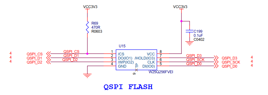
原理图#
原理图部分不需要关心,由总线驱动部分去完成。
设备树#
打开system-user.dtsi文件,在根目录外添加下面的节点:
&flash0 {
compatible = "w25q256";
};
qflash节点在zynq的设备树中已经存在了,我们只要改一下其中compatible属性即可。
驱动程序#
使用 petalinux新建名为”ax-spi-drv”驱劢程序,并执行 petalinux-config -c rootfs 命令选上新增的驱动程序。
在ax-spi-drv.c文件中输入下面的代码:
#include <linux/err.h>
#include <linux/errno.h>
#include <linux/device.h>
#include <linux/mtd/mtd.h>
#include <linux/mtd/partitions.h>
#include <linux/spi/spi.h>
#include <linux/spi/flash.h>
#include <linux/types.h>
#include <linux/kernel.h>
#include <linux/ide.h>
#include <linux/init.h>
#include <linux/module.h>
#include <linux/cdev.h>
#include <linux/fs.h>
#include <linux/fcntl.h>
#include <linux/platform_device.h>
#include <asm/mach/map.h>
#include <asm/uaccess.h>
#include <asm/io.h>

/* 驱动个数 */
#define AX_FLASH_CNT  1
/* 设备节点名称 */
#define AX_FLASH_NAME "ax_flash"

/* Flash操作命令 */
#define CMD_WRITE_ENABLE    0x06
#define CMD_BULK_ERASE      0xc7
#define CMD_READ_BYTES      0x03
#define CMD_PAGE_PROGRAM    0x02
#define CMD_MAX                 5

struct ax_qflash_dev {
    dev_t   devid;              //设备号
    struct  cdev cdev;          //字符设备
    struct  class *class;       //类
    struct  device *device;     //设备
    int     major;              //主设备号
    void    *private_data;      //私有数据, 获取spi_device
    char    cmd[CMD_MAX];       //SPI命令和地址
};

struct ax_qflash_dev ax_qflash;

static int ax_spi_write(struct ax_qflash_dev *dev, loff_t addr, const char *buf, size_t len)
{
    int ret;
    char cmd_buf[1] = {0};
    struct spi_device *spi = (struct spi_device *)dev->private_data;
    struct spi_transfer trans[2] = {0};
    struct spi_message msg;
    spi_message_init(&msg);

    /* 写使能 */
    cmd_buf[0] = CMD_WRITE_ENABLE;
    spi_write(spi, cmd_buf, 1);

    dev->cmd[0] = CMD_PAGE_PROGRAM;
    dev->cmd[1] = addr >> 24;
    dev->cmd[2] = addr >> 16;
    dev->cmd[3] = addr >> 8;
    dev->cmd[4] = addr;

    trans[0].tx_buf = dev->cmd;
    trans[0].len = CMD_MAX;
    spi_message_add_tail(&trans[0], &msg);

    trans[1].tx_buf = buf;
    trans[1].len = len;
    spi_message_add_tail(&trans[1], &msg);

    ret = spi_sync(spi, &msg);

    return ret;
}

static int ax_spi_read(struct ax_qflash_dev *dev, loff_t addr, const char *buf, size_t len)
{
    int ret;
    struct spi_device *spi = (struct spi_device *)dev->private_data;
    struct spi_transfer trans[2] = {0};
    struct spi_message msg;
    spi_message_init(&msg);

    dev->cmd[0] = CMD_READ_BYTES;
    dev->cmd[1] = addr >> 24;
    dev->cmd[2] = addr >> 16;
    dev->cmd[3] = addr >> 8;
    dev->cmd[4] = addr;

    trans[0].tx_buf = dev->cmd;
    trans[0].len = CMD_MAX;
    spi_message_add_tail(&trans[0], &msg);

    trans[1].rx_buf = buf;
    trans[1].len = len;
    spi_message_add_tail(&trans[1], &msg);

    ret = spi_sync(spi, &msg);

    return ret;
}

/* open函数实现, 对应到Linux系统调用函数的open函数 */
static int ax_flash_open(struct inode *inode, struct file *filp)
{
    /* 设置私有数据 */
    filp->private_data = &ax_qflash;
    return 0;
}

/* read函数实现, 对应到Linux系统调用函数的read函数 */
static ssize_t ax_flash_read(struct file *file, char __user *buf, size_t size, loff_t *offset)
{
    /* 获取私有数据 */
    struct ax_qflash_dev *dev = (struct ax_qflash_dev *)file->private_data;
    /* 读取数据buffer */
    char b[100] = {0};
    int ret = 0;

    /* 读取数据 */
    ax_spi_read(dev, 0, b, 100 > size ? size : 100);

    /* 把读取到的数据拷贝到用户读取的地址 */
    ret = copy_to_user(buf, b, 100 > size ? size : 100);
    return 0;
}

/* write函数实现, 对应到Linux系统调用函数的write函数 */
static ssize_t ax_flash_write(struct file *file, const char __user *buf, size_t size, loff_t *offset)
{
    /* 获取私有数据 */
    struct ax_qflash_dev *dev = (struct ax_qflash_dev *)file->private_data;
    /* 写入数据的buffer */
    static char user_data[100] = {0};
    int ret = 0;
    /* 获取用户需要发送的数据 */
    ret = copy_from_user(user_data, buf, 100 > size ? size : 100);
    if(ret < 0)
    {
        printk("copy user data failed\r\n");
        return ret;
    }

    /* 写入数据 */
    ax_spi_write(dev, 0, user_data, 100 > size ? size : 100);

    return 0;
}

/* release函数实现, 对应到Linux系统调用函数的close函数 */
static int ax_flash_release(struct inode *inode, struct file *filp)
{
    return 0;
}

/* file_operations结构体声明 */
static const struct file_operations ax_flash_ops = {
    .owner = THIS_MODULE,
    .open  = ax_flash_open,
    .read  = ax_flash_read,
    .write = ax_flash_write,
    .release = ax_flash_release,
};

static int ax_spi_probe(struct spi_device *spi)
{
    char cmd_buf[1] = {0};
    printk("flash probe\r\n");

    /* 构建设备号 */
    alloc_chrdev_region(&ax_qflash.devid, 0, AX_FLASH_CNT, AX_FLASH_NAME);

    /* 注册设备 */
    cdev_init(&ax_qflash.cdev, &ax_flash_ops);
    cdev_add(&ax_qflash.cdev, ax_qflash.devid, AX_FLASH_CNT);

    /* 创建类 */
    ax_qflash.class = class_create(THIS_MODULE, AX_FLASH_NAME);
    if(IS_ERR(ax_qflash.class))
    {
        return PTR_ERR(ax_qflash.class);
    }

    /* 创建设备 */
    ax_qflash.device = device_create(ax_qflash.class, NULL, ax_qflash.devid, NULL, AX_FLASH_NAME);
    if(IS_ERR(ax_qflash.device))
    {
        return PTR_ERR(ax_qflash.device);
    }

    ax_qflash.private_data = spi;
    /* 擦除 */
    cmd_buf[0] = CMD_BULK_ERASE;
    spi_write(spi, cmd_buf, 1);
    return 0;
}

static int ax_spi_remove(struct spi_device *spi)
{
    /* 删除设备 */
    cdev_del(&ax_qflash.cdev);
    unregister_chrdev_region(ax_qflash.major, AX_FLASH_CNT);
    /* 注销类 */
    device_destroy(ax_qflash.class, ax_qflash.devid);
    class_destroy(ax_qflash.class);
    return 0;
}

static const struct spi_device_id ax_id_table[] = {
    {"w25q256", 0},
    { }
};

static const struct of_device_id ax_of_match[] = {
    { .compatible = "w25q256" },
    { }
};

static struct spi_driver ax_spi_driver = {
    .probe = ax_spi_probe,
    .remove = ax_spi_remove,
    .driver = {
        .owner = THIS_MODULE,
        .name = "w25q256",
        .of_match_table = ax_of_match,
    },
    .id_table = ax_id_table,
};

static int __init ax_init(void)
{
    return spi_register_driver(&ax_spi_driver);
}

static void __exit ax_exit(void)
{
    spi_unregister_driver(&ax_spi_driver);
}

module_init(ax_init);
module_exit(ax_exit);

/* 驱动描述信息 */
MODULE_AUTHOR("Alinx");
MODULE_ALIAS("qspi flash");
MODULE_DESCRIPTION("I2C FLASH driver");
MODULE_VERSION("v1.0");
MODULE_LICENSE("GPL");
45~102行是spi-flash的读写实现。读写操作都需要分两步走,第一步是发送命令和从机的目标地址,第二部是发送待发送数据的地址或者读出数据的buffer。注意第一步中发送buffer都是trans. tx_buf,第二步中,发送tx_buf,读取为re_buf。发送步骤就像之前说的,先打包spi_transfer,再添加到spi_message中,使用spi_sync函数发送。
113~149行是字符设备的read、write函数实现,和 I2C驱动 那一章节中的实现基本一样。所以后面的测试也可以直接用**I2C驱动** 那一章节中的测试程序。
166~197行是probe实现,匹配成功后就会执行。probe中168~190行首先注册字符设备。然后192行把spi赋值给设备结构体的私有变量。
之后就是匹配方式的实现,这部分与至今为止的总线框架相比,除了类型不同,其他都是一样的。
测试程序#
可以直接使用 I2C驱动 章节的测试代码。
运行测试#
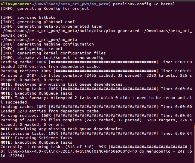
petalinux定制的系统中,默认是不包含spi总线驱动的,需要使用命令配置,方法如下:
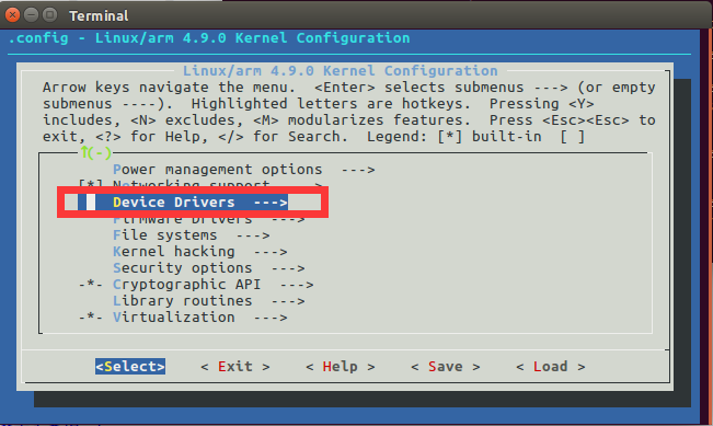
在终端中输入命令配置内核petalinux-config -c kernel,弹出配置界面如下:
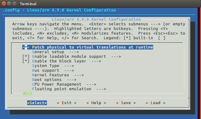
按回车进入配置界面中的Device Drivers子选项
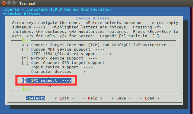
选择SPI support
先按空格键给SPI support选项打上*号,然后按回车进入选项。
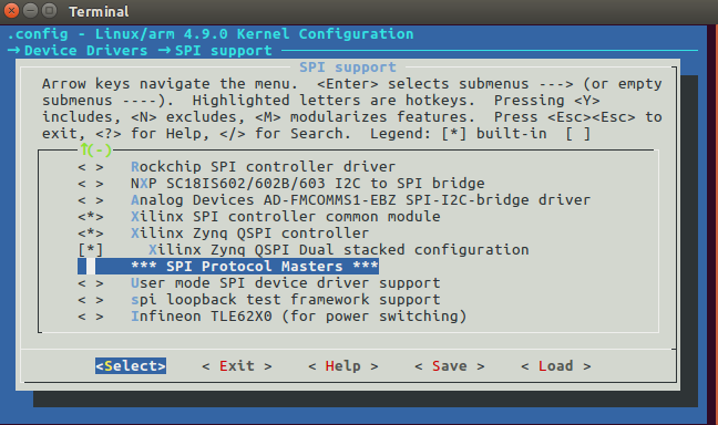
选择xilinx的spi总线驱动,选择save,然后exit
测试方法步骤如下:
mount -t nfs -o nolock 192.168.1.107:/home/alinx/work /mnt cd /mnt mkdir /tmp/qt mount qt_lib.img /tmp/qt cd /tmp/qt source ./qt_env_set.sh cd /mnt insmod ./ax-spi-drv.ko cd ./build-ax_i2c_test-ZYNQ-Debug/ ./ax_i2c_test /dev/ax_flash |
IP 和路径根据实际情况调整。
串口工具中的调试结果如下:
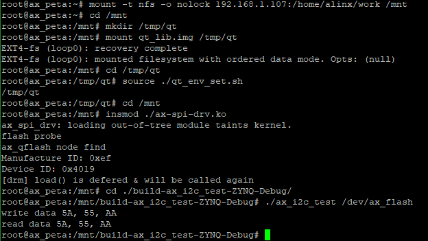
读写结果一致,试验成功。